In this article, we will discuss how to maximize the value from the use of emulation systems on SoC development projects.
What has changed in emulation usage models
For many years, the principal emulation system use model was to take simulation-debugged RTL and map it as "early silicon" in reprogrammable hardware, and then operate it with real software while connected to a real physical environment. The goal was to gain confidence that the SoC would actually work as intended before committing to silicon. This verification methodology is referred to as in-circuit emulation, or ICE. In ICE, with the emulator running much slower than the connected physical environment, each system-level interface typically requires a data buffering mechanism to match the emulation system to the environment. In such environments with design specific hardware configurations comprising the verification environment, the emulation system access is essentially restricted to a single project at a time.
Maximizing the value of today's emulation systems requires taking different approaches than those of the past- namely: the use of virtual test environments and optimization of verification flow via a better mix of verification methods.
Virtual test environments simplify the use model on today's complex SoCs and increase accessibility
There has been a large shift from ICE to transaction-based accelerated verification in which the emulated DUT interacts at very high speeds with a virtual environment. The key driver for this is the ever increasing number of external interfaces on SoCs - a tablet, wireless phone, or digital TV SoC may have >20 external connections, running the gamut of peripheral and communications protocols.
The implementation of a transaction-based verification methodology provides many benefits over an in-circuit emulation methodology. The entire design is contained within its hardware and its associated PC: no target board is required, nor external cabling, level shifters or speed-adapters. Instead, the external environment is modeled as a group of transactor models for each aspect of the SoC interface; e.g. PCIe, USB, keypad, LCD display and camera sensors. The front end of each transactor that communicates at a high-level of abstraction with each peripheral is modeled in C on the PC (Figure 1).
Emulation transactors (VIP) typically are comprised of three elements. At the core is a synthesizable protocol specific element, usually a BFM or full IP implementation that is placed in the emulation hardware along with the DUT. Advanced systems like ZeBu have dedicated resources for these elements, to optimize the performance in the system (Figure 2). In the normal two-way data flow, communications between the host and DUT in the emulator are transaction-based, maximizing the system performance. On the downstream side, the protocol block converts the transaction-level signals to pin-level signals, and interfaces to the DUT's protocol specific physical interface.
A well architected emulation system can accommodate dozens of such protocol specific transaction-level interfaces.
The beauty of transaction-based verification methodology is that all the interfacing from the DUT to the external test environment is software configurable and downloadable. Changing the system from one block to another, or testing multiple blocks in parallel, or even shifting from one SoC design to another, can all be done through software configurations from anywhere on a network. The system, accessed as a networked resource, offers much more flexibility and value than if used for ICE based verification.
Use the right methodology at the right time
A factor in obtaining the best out of the emulation system is to use a mix of verification methods appropriate to different stages on a project. During early architectural design, high-level models in virtual prototypes are used to make tradeoffs and optimize different parts of the design. With much of today's SoCs consisting of major blocks being re-used from prior designs or licensed from third parties, there is considerable RTL available very early in the project.
In such cases, hybrid emulation - emulation environment can be used where the RTL models can be exercised in the emulator, and the blocks of the design are exercised in the virtual prototype. The full visibility into the RTL within the emulator can prove extremely useful in identifying implementation problems in the RTL blocks while exploring your design alternatives.
Once RTL is all available, typically block-level designs are initially tested with simulation. Once the bug discovery frequency drops to a reasonable level, maybe a bug a day, users frequently will move the block-level testing to an emulation system and begin running more exhaustive tests at speeds unattainable with simulation. At this point, firmware may be introduced to verify the initial hardware - software interactions.
After running initial regression tests in simulation on the entire SoC, many teams quickly move their full SoC testing to emulation where they can greatly expand the real-time cycles on their designs. Typically at this point, early versions of drivers and other low level software are available and testing can begin moving into realistic system test scenarios.
When the RTL design is stable enough, it's time to give emulation system access to the software development teams, whom up to that point may have been using non-cycle accurate transaction-level models for development. It may also be optimal to provide multiple, high performance FPGA-based prototypes, like our HAPS systems, to the software team to accelerate their development.
Conclusion
Getting the most value and productivity of your emulation system generally requires that you
*Leverage virtual test environments to simplify the use model and increase accessibility
*Adopt the most appropriate verification methodology at the right time to optimize your entire verification flow.
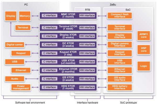
Figure 1: The front end of each transactor that communicates at a high-level of abstraction with each peripheral is modeled in C on the PC
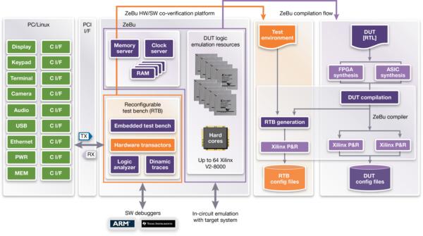
Figure 2: The back end that converts high-level commands into bit-level protocols is mapped to hardware within the emulation system's RTB architecture
DIGITIMES' editorial team was not involved in the creation or production of this content. Companies looking to contribute commercial news or press releases are welcome to contact us.